DCC Decoder Wiring Diagrams for Non-DCC Ready Locomotives

We’re working on a short tutorial looking at DCC decoder installation in older locomotives, such as Lima and Hornby, that are powered by ringfield/pancake-style motors.

To accompany the tutorial, we’ve produced a PDF containing a series of basic wiring diagrams to help with the installation process. They cover the more modern can-style motors (as found in Bachmann, Heljan, Dapol etc.) as well as the older ringfield ones (similar to those found in many Hornby and Lima models).


There’s also a basic diagram for directional lighting and a single Aux channel, such as the Aux 1/green wire available on most low/mid-range decoders, such as Hornby’s entry level R8249 8-pin variety.

The wiring principles would be the same for older ‘grain of wheat’ bulbs, although the resistor value would need to be altered to suit the bulb and track voltage.

You can download the PDF by clicking here.

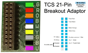
TCS 21 Pin DCC Breakout Adaptor

We published a video in January 2018 describing how to convert an 8-pin Hornby TTS decoder for use in a 21-pin chassis.

In that video, we used a LaisDCC 21 to 8-pin adaptor, customised by removing the 8-pin socket, to allow the decoder to be plugged into a Bachmann Class 47.

While that method is still totally valid and remains the cheapest option (as of today’s prices), we have subsequently discovered a TCS-brand 21-pin breakout board which can be used for the same purpose.

These TCS adaptors are more expensive than the method outlined in our earlier video, but easier to use and require no real preparation. They only come in packs of five, however, and at about £20 per pack, if you only need one, they’re pricey.

We’ll probably do a quick video follow up in due course as we have another TTS chip to convert, but for the time being, as we’ve yet to find any instructions online, here’s a pin-out wiring diagram for the TCS 21-pin adaptor…

21 Pin DCC Breakout Adaptor Pinout Wiring Diagram