Strathpeffer Junction YouTube Model Railway Channel Layout Cards

I was chatting to Paul at the Galgorm Hall model railway layout a few weeks back about railway modelling on YouTube, and model making and creativity online more generally.

One thing that we both loved about other maker channels, particularly amongst the woodworking community, is that folk share ‘shop cards’ with each other as a way to support other channels and give visual ‘shout outs’.

So, we decided we’d knock up some ‘layout cards’ for our own respective model railway YouTube channels and share them with each other to get the ball rolling.

And no sooner had we exchanged cards, when Simon from Liverton Central dropped us a line to get involved – and so it began!

I’ve also put together a small noticeboard, which I’ll hang on the wall in the loft and fill up with cards as and when they arrived. I’ve put together a short video explaining the thoughts behind this initiate – link below – and we’d love it if you’d like to get involved.

How to get a Strathpeffer Junction Layout Card

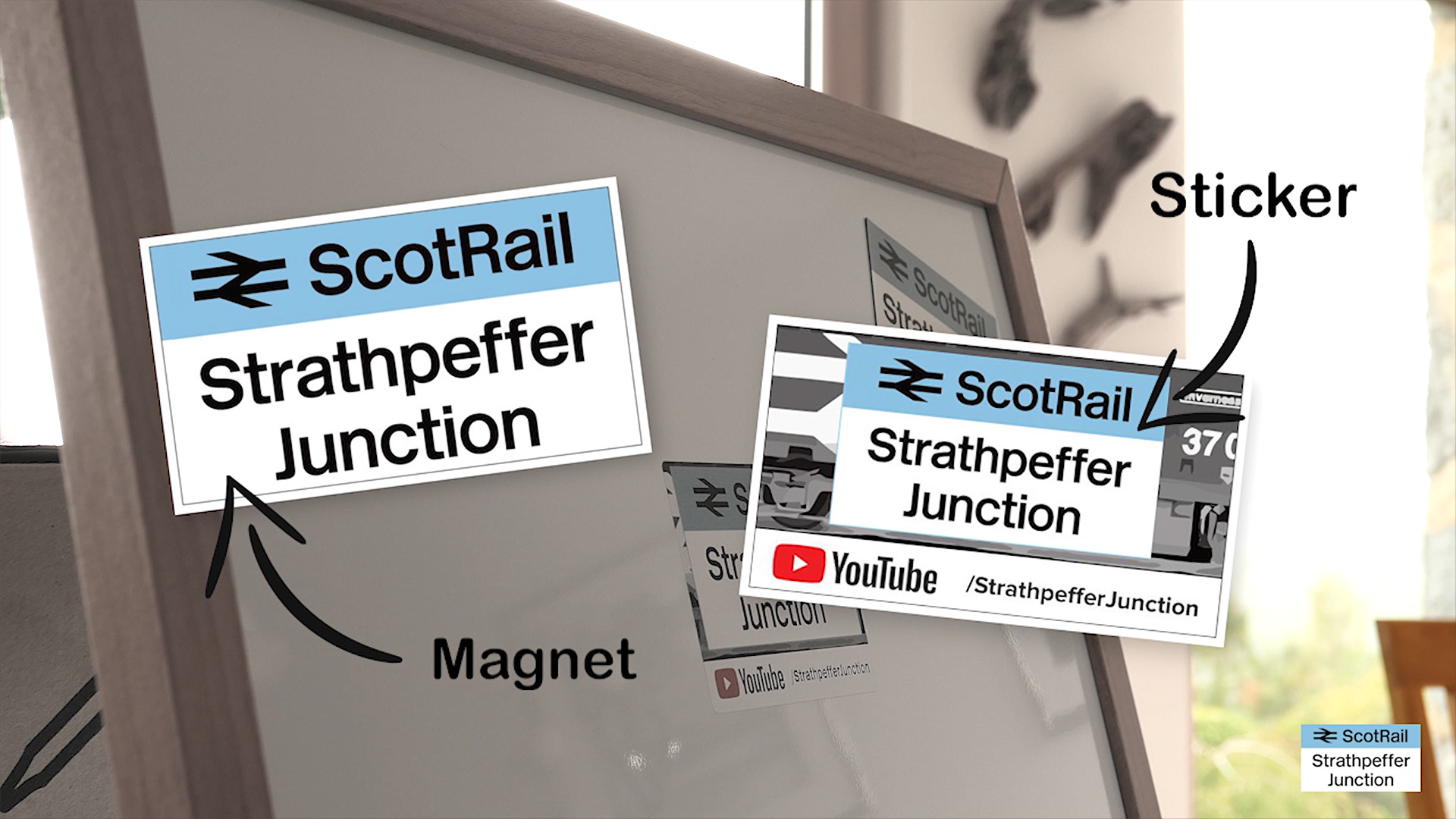
If you’d like a Strathpeffer Junction layout card, please click on the link below to send me your details. Please let me know if you’d prefer a magnet or sticker. Both variants now feature the Strathpeffer Junction station sign and YouTube design (see image above).

I originally had 50 cards to send out free of charge and with free UK/EU postage initially. I only have a handful of that batch left. Once the initial 50 have gone, I’ll happy send out the remaining cards in exchange for a stamped addressed envelope or contribution towards postage, or in exchange for your own card, which I’ll happily add to my wall of layout cards.

To get your Strathpeffer Junction card, please click here to send me your details. Make sure to include a UK/EU postal address. If you live further afield, I’m happy to send out a card if you cover the postage.

Got a layout card for your own channel?

I’d absolutely love to collect layout cards from other model railway YouTubers – be they in the UK or further afield – and add them to my board. If you’d like to send me one or you’d like to exchange one for one of my own cards, please drop me a line.

Wiring Diagram for DCC Decoder Test Board & Rolling Road

This is a wiring diagram for the decoder/loco test boar and rolling road featured on this website. Your own test board wiring requirements will vary depending on the components that you use and also the specifics of your design. The diagram provided above is only a guide and you must work out your own wiring needs yourself to avoid costly damage to programmers, testers and decoders.

Making a Test Board & Rolling Road for Analogue & DCC Model Locos

I’ve been doing an increasing number of DCC decoder installations and model locomotive repair jobs – both for myself and others – and setting up my tester and rolling road each and every time I needed them was becoming a bit tiresome (not to mention the rat’s nest of cables).

After pulling what’s left of my hair out for the final time, I decided to put together a small loco and decoder test board, incorporating my LokProgrammer and SPROG, as well as accommodating off-board control integration (DCC and DC/Analogue).

The board also features a rolling road, using DCC Concepts rolling road modules, and my own take on a means to permanently integrate them into a test set up and improve usability, using acrylic sheet, spacers and screws.

You can download a PDF version of the wiring diagram for the test board featured in the video via the link below:

Icon

Wiring Diagram for DCC Decoder Test Board & Rolling Road 5.98 MB 1600 downloads

This is a wiring diagram for the decoder/loco test boar and rolling road featured...

This is only one way of approaching a decoder test board setup and there other examples out there. I do recommend that you consider something like this if you’re intending to do a lot of decoder installation and maintenance – it saves a lot of time and hassle!

CORRECTION: in the video, I mention the acrylic/perspex sheet as being 6mm when it is actually 4mm. A thickness of 6mm is likely to be too thick and may interfere with the wheel flanges.

Project Components

You can buy some components for this how-to project via the links below. Buying via Amazon affiliate links means I get a (very) small donation and helps to support the website and channel:

– DCC Concepts rolling road: https://amzn.to/2C1IB6t
– Red and black wire pack: https://amzn.to/2C1Infx
– Green 2-pin terminal plugs/sockets: https://amzn.to/2PiVfiW
– Peco straight track: https://amzn.to/2LGgPM7
– A4 clear acrylic sheet (4mm thick): https://amzn.to/2Cae1Yk
– M5x8mm black nylon spacer: https://amzn.to/2Pq7tX4
– A4 plywood 12mm: https://ebay.us/LGRLYW
– A4 plywood 3mm: https://amzn.to/2C03bE2
– ESU decoder tester: https://ebay.us/aBLzSi
– SPROG dcc module: http://www.sprog-dcc.co.uk
– Green power panel-mount socket/plug: https://ebay.us/nBLfXz
– DC power-style socket: https://ebay.us/nBLfXz
– 3 position, 2-pole switch: https://ebay.us/WyKD3b

3D Printer STL Files

If you’ve got a 3D printer, you can download STL file for the 3D-designed parts for free and print yourself a copy:

Switch box/enclosure: https://skfb.ly/6B6Cy
SPROG3 cradle: https://skfb.ly/6B6DY

Please note: If you choose to follow any of the steps or suggestions outlined in the video, you do so at your own risk and any damage or injury to yourself, your models, your equipment or others is your own responsibility. Your own test board wiring requirements will vary depending on the components that you use and also the specifics of your design. The diagram provided above is only a guide and you must work out your own wiring needs yourself to avoid costly damage to programmers, testers and decoders.