

Earlier in the year, we started an in-depth mini-series on a variety of upgrades to an old Lima Class 47 loco. On 8 June 2018, we published the fourth and fifth videos in the series, which focus on replacing the ringfield/pancake motor with a brand new CD/DVD drive motor.
In Part A, we look at dismantling the old motor, removing the gears for cleaning, adapting the plain bearing to accommodate a smaller drive shaft and positioning the new motor ready for gluing.
Part B then focuses on fixing the motor into place, creating a small diode array to drop some volts so that the motor is less stressed by higher voltages and then wiring it all up to the DCC decoder.
These are detailed, step-by-step videos. If you want a brief overview, you’ll find other options on YouTube and elsewhere. The methods used in the videos are not necessarily the only way to do it, nor necessarily the best.
Diode voltage dropper
In the project, we use a simple diode circuit to drop down voltage to the motor by ~2V. This is to help reduce potential for the 6V motor to be burnt out by over-voltage when running at higher speeds.
We produced a quick reference diagram for the diode voltage dropper, which should hopefully make the soldering process straightforward. The circuit is not mandatory per se and decoders with CV5 may be able to keep voltage down via other means, but we still recommend it.

Note: our diode circuit features SMD (surface mount) components, but the configuration is the same for the through-hole variety; you can just twist the legs together and solder, rather than using copper-clad circuit board.
Some technical considerations
The 10mm CD/DVD drive motor should work in most Lima models locomotives of the following OO gauge classes: 08, 09, 31, 37, 40, 47, 52, 59, 60, 66 and 92. Other models may be able to accommodate a 12mm motor, but you must check dimensions yourself first.
The replacement motor is a 12000rpm, 6V, 0.03A DC motor. The output from a DCC decoder or a DC controller can reach 12V DC (sometimes a little higher) at the top end. In order to avoid motor burn-out and prolong motor life:
1. Diodes should be used to reduce voltage (as shown in the video),
2. DCC decoders should have their CV5 value reduced (if available), and
3. Top speeds should be kept to a minimum and run at higher speeds for short periods only.
Parts & consumables
To save you having to trawl the web for the parts and consumables used in the videos, we’ve compiled a few Amazon affiliate links for your convenience:
* 10mm 6V motor: https://amzn.to/2HtkpYa
* 8-tooth, 2mm ID/5mm OD gears: https://amzn.to/2HtWI1C
* 2.5mm OD brass tube here: https://tinyurl.com/2-5mm-brass-tube
* Surface mount (SMD) rectifier diodes: https://amzn.to/2JnqkDE
* Through-hole rectifier diodes: https://amzn.to/2sQweSH
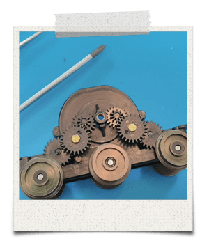
Ringfield motor gear layout
We always recommend that you take a photo of things before dismantling anything. However, just in case you’ve taken your motor apart and forgotten which way round the gears go, here’s a photo we took during one of our conversion jobs…
Please note: I’ve drawn upon ideas and suggestions from a range of channels and people, as well as implementing my own. If you choose to follow any of the steps outlined in the video, you do so at your own risk and any damage to yourself, your models or your equipment is your own responsibility.


You must be logged in to post a comment.