Someone asked me recently about DCC bus terminators (or, more accurately, ‘filters’ or ‘snubbers’), whether you should use them and, if so, how to wire them. So, I knocked up a quick diagram for them and I’ve uploaded it to the website in case it’s of use to others. It’s a very simple circuit!
There are different schools of thought on whether a terminator/filter/snubber is required. My own take is that for most small to medium layouts, they’re probably not necessary as a default. However, for bigger layouts or if you’re having reliability issues/unexpected performance problems, it’s probably worthwhile installing them.
If your DCC bus is a loop, then no filter is required (it’s also moot whether this is a good way to do it or not). If it’s a single run, then you only need a single filter at the end. If you’ve got for a T-shaped bus or you have more than one bus, then you’ll need a filter for the end of each run. Simples!
Note: Some people have reported conflicts and false positives with block/occupancy detection when a filter is installed – it’s something to be aware of. It perhaps also goes without saying, but remember that if you’re using block or occupancy detection technology, the filter should be installed on the end of the DCC bus and not on a leg from the detector module.
Welcome to Part 2 of our in-depth mini-series looking at improvements and upgrades to Hornby TTS sound decoder-fitted locomotives. In Part 1, we looked at speaker upgrades, and in this second part we’re looking at making a stay alive capacitor unit and fitting it to the decoder.
Whilst focused on the Hornby TTS decoder, the principles and steps outlined in these videos are applicable for most other stay alive scenarios, including other types of decoder, coach lighting circuits, end of train (EOT) lamps and so on. It’s ideal viewing for anyone interested in this areas of railway modelling.
Making the Stay Alive/Keep Alive Capacitor Unit
As well as showing you how to make the stay alive unit itself and assemble all of the components, in this video there’s a brief explanation of the background to stay alive devices generally and the role that each of the components plays in the overall circuit.
+ Video Contents +
00:00 – Video introduction
01:08 – Intro to making a stay alive unit
02:18 – Overview of the components required
04:11 – Using resistors to manage in-rush
05:00 – The components in detail
06:26 – Circuit diagrams
08:40 – A quick word of capacitor sizes
10:58 – Putting it all together: soldering
15:40 – Adding hookup wires & heat shrink
17:22 – The finished article
Fitting the Stay Alive Unit to the TTS Decoder
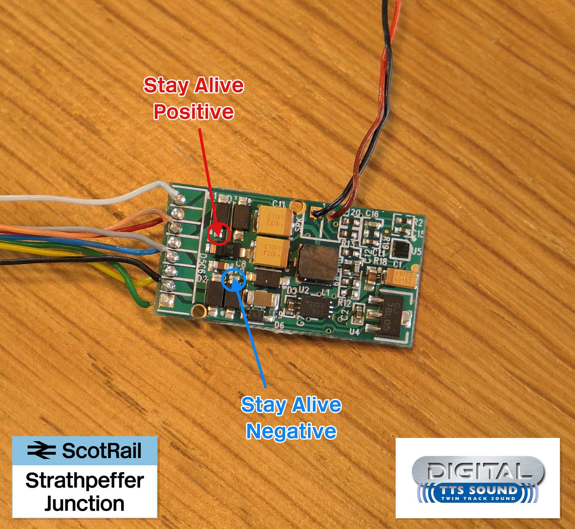
In this final video, we look at adding the stay alive/keep alive unit that we made to Hornby’s TTS sound decoder. We look at where to solder the two wires and also how to adjust CVs on the decoder to ensure that the stay alive unit functions correctly.
While the specific steps relate to Hornby’s TTS decoder, if you wanted to add a stay alive unit to their entry level R8249 decoder, the steps would be fairly similar (although the negative leg would have to be soldered directly to the negative side of the rectifier). If you’re using a different brand of decoder, the principles will be very similar, but the solder points will be different.
+ Video Contents +
00:00 – Introduction
00:20 – A quick recap
01:20 – Examining the decoder
06:08 – Soldering it all together
14:52 – Testing the solder work
16:10 – Fitting it all into the chassis
18:05 – A word about CV settings
19:08 – Testing the stay alive unit
20:53 – Conclusions
Please note: the steps involved in fitting the unit do require a steady hand and competence with a soldering iron. Working with DCC decoders and tiny surface-mount components leaves little margin for error and it is very easy to permanently damage sensitive electronics if you are not extremely careful.
Circuit Diagrams
We’ve produced a couple of circuit diagrams to accompany this tutorial series. You can download copies for free using the links below:
You can buy items used in these tutorials using the affiliate links below. Using these links helps to support this website and our associated YouTube channel and is very much appreciated.
This project does require a steady hand and competence with a soldering iron. Working with DCC decoders and tiny surface-mount components leaves little margin for error and it is very easy to permanently damage sensitive electronics if you are not very careful. If you choose to follow any of the steps or suggestions outlined in the video, you do so at your own risk and any damage or injury to yourself, your models, your equipment or others is your own responsibility.
The is the first in a two-part series on upgrades and improvements that can be made to a Hornby Class 37 locomotive with TTS sound.
In the second video, we’ll look at adding stay-alive capabilities to help keep the running smooth and steady, but for now, we’re upgrading the stock speaker to something a little better…
The steps outlined in this video are applicable to all TTS sound decoders (and many others). The only differences being that in some locomotives – not least most steam locos – the space inside can be rather limited and you may not be able to fit such a large speaker into the body.
Remember that in all cases where a Hornby TTS decoder is used, you must also use a 8 Ohm speaker (or two 4 Ohm speakers in series, adding up to 8 Ohms). This is different to LokSound V4 decoders, which can use a 4 Ohm or 8 Ohm speaker.
Speaker impedance and decoder specifications for all common sound decoders are explained in more detail in our free guide, which you can download here:
Please note: If you choose to follow any of the steps or suggestions outlined in the video, you do so at your own risk and any damage or injury to yourself, your models, your equipment or others is your own responsibility.


You must be logged in to post a comment.